Showing posts with label CNC. Show all posts

Tuesday 8 May 2007

Successful milling

The new metalwork did the trick. It completely solved the snatching problem I had previously. I managed to mill this test shape out of 2.5mm polystyrene, at least that is what I thought it was. I found a site: www.tempatron.co.uk/weld_rods.htm which describes how to identify plastic by setting fire to it and the closest match is ABS, so it may in fact be ABS.


As you can see it has nice clean edges and it measures 34.07mm by 60.02mm by my cheap electronic calipers so is pretty accurate.

Getting the feed rate and cut depth right took a few attempts. The problem was that the plastic kept melting as you can see here :-


I found that with a cut depth of 0.5mm I could only feed at about 0.2mm per second to prevent melting. Reducing the cut depth to 0.1mm allowed me to increase the feed to 10mm per second which is ten times more productive. I probably could have pushed it further but I am not particularly interested in making anything from this material. Here is a video of the test :-


I now have a small but highly accurate CNC milling machine. A few improvements are definitely needed :-
  1. Dust extraction!
  2. Tool height detector
  3. Spindle motor control and stall detect

Wednesday 2 May 2007

More trouble at' mill

Well things did not quite go to plan. The first problem was that most of my milling bits have ends that are smaller than the top of their shafts so they cannot go very deep. The only exception is a 1/8th inch end mill that came as part of my PCB routing set. It is intended for routing PCB board outlines. The problem was that my first drill did not have a collet big enough to take it. The Minicraft replacement has a three jaw chuck which will. So plan B, I fitted the Minicraft drill into the bottom MDF mount intended for my other drill. Rather than tackle the big block of hard plastic I thought I would try it out on a sheet of scrap polystyrene first. I stuck this down with double sided sticky tape.


I started with a feed rate of 4mm per second. This was far too high as it stalled the drill. I dropped down to 1mm per second and then to 0.5mm. At this point it seemed to be able to handle the cutting but it kept snatching horribly. I dropped down to 0.1mm per second which took ages but it still snatched. I only got as far as the first corner before I aborted. You can see that after the first 15mm it no longer goes right through the plastic. This is because I did not tighten the chuck enough and the bit slipped.

I might be wrong but I think the snatching is due to the set up not being rigid enough. I had already identified that as a weak point and the new motor mount was aimed at improving it. The first drill was supported at both ends but this one is too short so it needs a much stiffer mount, which is what I was trying to make! Perhaps the end mill bit is not suitable for styrene, or perhaps styrene is not very machinable, or perhaps the RPM is too high, or too low. Can you tell I am a bit out of my depth here?

One thing I can do to improve stiffness is to replace the 2mm aluminium plate with the 6mm slab I already bought for the job. I was putting that off until I got the new mount so as not to have to drill two sets of holes in it.

Another thing I might try is to make a top mount out of PolyMorph.

Tuesday 1 May 2007

On the right path

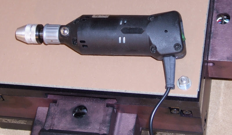
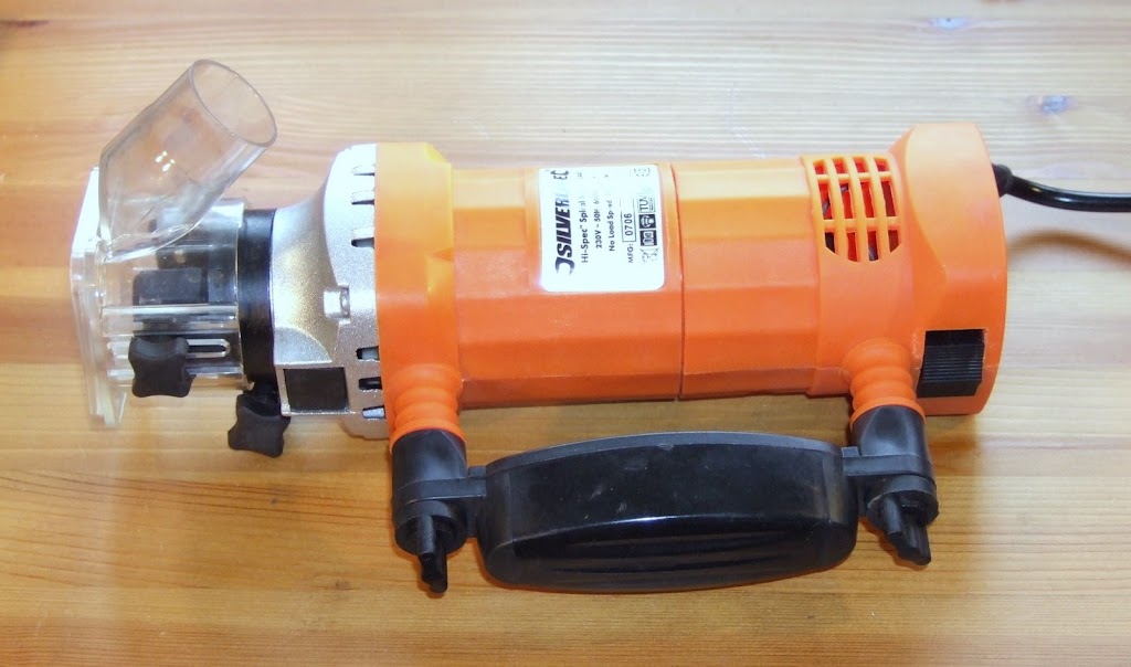
Having tried a cheap mini drill as a router and found it lacking I ordered a cheap laminate trimmer to try instead. While I was waiting for it to arrive I remembered that I had inherited a Minicraft drill from my aunt.


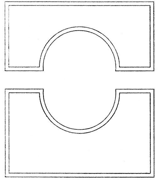
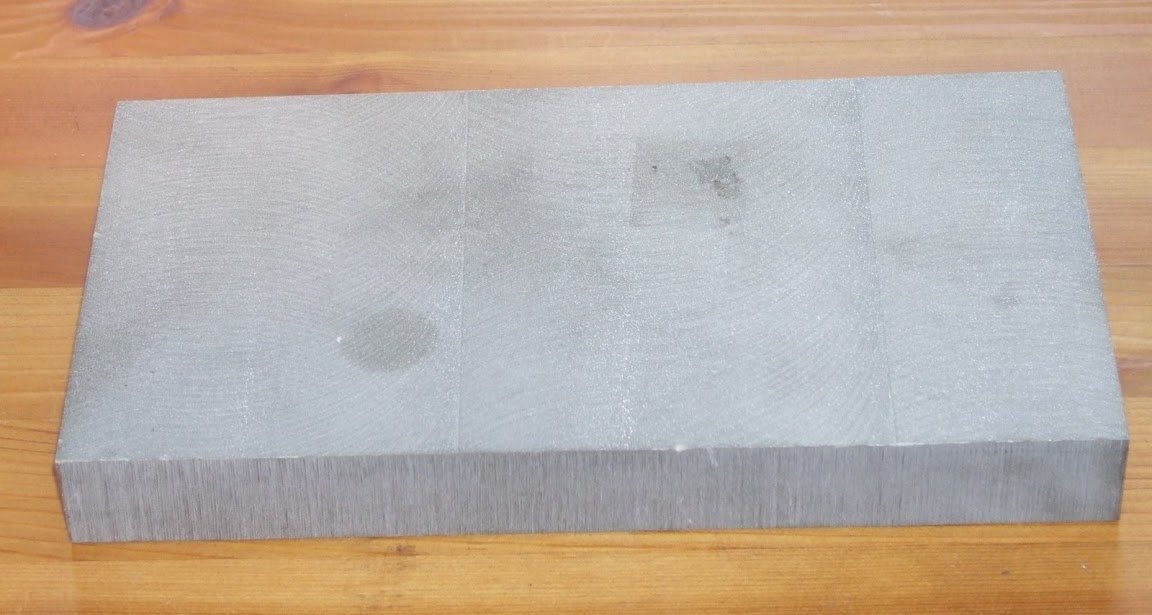
To my surprise this seems quite promising. The bearing is solid and it revs to 20000 RPM without too much noise. It also has the advantage that it is small and light so is suited to a multi-headed machine. I decided to see if I could use the first drill to mill a mount for the new one out of a block of hard plastic. I designed a simple two part clamp using Visio.


I represented the outline of the parts using a couple of Python lists.
bottom_clamp = [Line(0,34), Line(13,34), Arc(30,34,47,34), Line(60,34), Line(60,0), Line(0,0)]
top_clamp = [Line(0,26), Line(60,26), Line(60,0), Line(47,0), Arc(30,0,13,0), Line(0,0)]
Line and Arc are simple classes with a do method which instructs HydraRaptor to move along the segment. E.g.
class Line:
def __init__(self,x,y):
self.end = (x,y)

def do(self,hydra):
hydra.feedto_xy(self.end)
It was then trivial to get HydraRaptor to draw the outlines with a pen using a for loop :-
for seg in outline:
seg.do(hydra)
However in order to be able to mill it out I need to create a tool path which is offset by the radius of the bit. This is a little harder than it sounds. It is easy enough to offset a line at right angles to its direction but then the ends no longer meet. A new intersection point has to be calculated and a different calculation is required for each possible pair of segment types. I decided to prove to myself that I could still do O-level maths and worked out the equations from scratch. A quick Google afterwards verified that they were correct before coding them up. Here is the "line to line" case http://local.wasp.uwa.edu.au/~pbourke/geometry/lineline2d/ and here is "line to arc" http://local.wasp.uwa.edu.au/~pbourke/geometry/sphereline/. The trick is to represent lines with a pair of parametric equations rather than simply y = a +bx to avoid having special cases for verticals.

Having done that I got HydraRaptor to draw the tool paths with the pen. Here is the result :-


The next step it to actually mill it. I am not sure how I am going to hold the plastic block down yet. I think I will try double sided tape and if that fails contact glue.

Monday 23 April 2007

Double chicken and egg

My spiral saw arrived at the weekend. Although it was dispatched the day after I ordered it, it took another 17 days to get here from Yorkshire. For some reason Business Post could not find the address. Have they never heard of Google maps ?!


Although it was only cheap it does seem to have pretty solid bearings so looks promising for routing. At 600W and revving at 30000 RPM it should rip through most things. I just hope my z-axis motor is strong enough to lift it at 1.6Kg. If it can't then I may have to counter-balance it with a weight and a pulley or else use a bigger motor like this one for example.


I don't have any torque data for it but, at 85mm diameter, it looks beefy.

I plan to make the extruder body by milling this material.


I don't know what it is but it seems very hard and rigid. My best guess is that it is some sort of epoxy type resin with possibly a metallic filler - it has a bit of a sparkle to it. I might be completely wrong though. Anybody know what it is?

The chicken and egg problem is that to make the extruder I need to use the router, but to make the router mountings I could do with using the extruder!

Sunday 1 April 2007

Worth the wait

The XY stage turned out to be a really nice piece of kit. It is an XYR-8080 from NEAT, details here. It also came complete with a pair of MDM7 stepper motor drivers. These are bipolar, constant current, micro-stepping with anti-resonant circuitry and opto isolated inputs, i.e. top of the range. Perhaps I should explain each of these terms :-

Bipolar versus Unipolar drive

Stepper motors usually contain two electromagnets which need to be energised in one of two magnetic polarities, giving four combinations or phases. If this is done with a single coil per electromagnet then the electronics must be able to drive a positive or negative current into each coil. This is bipolar drive and requires four transistors per coil, i.e. eight per motor. Alternatively the coils can be centre tapped which effectively creates two coils per electromagnet wound in opposite directions. One of these can be energised at a time to produce opposite magnetic fields. This only requires one transistor per half coil, i.e. four per motor. The advantage of unipolar is that the electronics are cheaper but as only half of the windings are energised at one time the amount of torque available from a given size of motor is less.

The field produced by an electromagnet and hence the torque of the motor is proportional to the number of turns times the current. The maximum current that can be applied is limited by the maximum allowable temperature rise. The heat generated in the windings is proportional to current squared times resistance. This means that if a unipolar motor is operated in bipolar mode then the maximum current is root two times less because the resistance of the full winding is double that of the half windings. However, the number of turns is doubled so the torque is root two greater.

Constant current versus constant voltage

The simplest way to drive a stepper is to apply a constant voltage to the coils. The problem with this is that when a voltage is applied to a coil the current builds up gradually at a rate proportional to the voltage divided by the inductance until it reaches the steady state defined by the voltage divided by the resistance. This causes torque to fall off with speed because at higher step rates the current does not get time to reach its full value before the next step.

A better driver system is to apply a much higher voltage to the coil to get the current to rise quickly and then turn it off when it reaches the correct value. The current then starts to fall at which point the voltage is applied again. This on / off switching occurs at a high enough frequency to avoid producing audible noise.

Micro-stepping

This is a technique to increase the number of steps per revolution by varying the current in the two windings in a sinusoidal fashion. In this case it increases the number of steps from 200 to 2000 per rev. As the screw threads have half an inch travel per rev this gives me a step size of a 4000th of an inch or just over 6 micrometers. The target for RepRap V1.0 aka Darwin is 0.1mm resolution so I am well within that that! The only downside is that the maximum travel is only 150mm in each direction compared to Darwin's 300mm.

Another advantage of micro-stepping is that it produces smoother running at low speeds.

Anti-resonance

Because the force applied by the motor increases as it is displaced from its resting position it behaves like a spring. This together with the mass of the rotor and the load forms a resonant system. If the step rate gets close to the resonant frequency oscillations build up and the motor gets out of step and / or stalls. This is a major problem with high speed operation of stepper motors. An anti-resonant drive monitors the drive waveforms to detect when resonance starts to occur and adjusts the drive current to dampen it down. This allows the motor to be stepped through its resonant band to achieve higher speeds. Clever stuff!

Opto isolated inputs

The step and direction inputs are electrically isolated from the drive electronics by opto couplers. This avoids heavy motor currents sharing the same ground path as the logic signals, which can cause signal corruption.
The XY stage also includes hall effect limit switches and 2000 step shaft encoders. A great find, the challenge now is to build a machine that does it justice.

Here it is being put through its paces with a signal generator on one axis.

It can easily handle step rates up 6kHz which is about 40mm per second. With a bit of ramp up and ramp down I think it would go well above 10kHz. Also I have the full windings connected for maximum torque. The motors are centre tapped so I have the option of using half the winding. This gives root two less torque but one quarter of the inductance, so should be better for higher speeds if needed.

Saturday 31 March 2007

Chicken and Egg

The problem with making machines that make themselves is how to make the first one! A bootstrap machine has to be made by hand first. This has come to be known as a RepStrap machine in the RepRap community. Lots of people are trying different approaches using whatever materials are easy to come by locally. Wood, Lego, Meccano, copper pipe and drawer slides have all been used by different RepStrappers. The machine needs three axes of motion and an extruder head to extrude molten plastic filament. Most RepStrap machines use threaded rod as a means of creating accurate linear motion from a stepper motor for the axes.

This was the approach I was planning to take when I started looking at this in mid January. I had a look at how professional CNC machines are put together and saw that the prices are a lot more than I wanted to pay but the accuracy and speed was a lot better than I could hope to achieve with drawer slides, etc. I had a quick look around to see if I could get anything second hand or from the surplus market. To my surprise I found an XY table on ebay for $400 which has a super small step size of 6 um but is able to move quickly and has very high stiffness.


This gave me the idea that I could make a very accurate machine that is also stiff enough to do milling. I found a Z axis on CNCzone for $150 and the project was born.