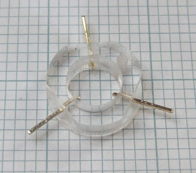
Things went well to start with. I milled a ring with three flats on it out of 6mm Perspex. I drilled into the flats and inserted three gold plated pins extracted from a 0.1" header.

I then milled a base which bolts into one corner of the tray on top of my XY table. It has a circular recess to locate the base of the contact ring and a blind hole to house the spring. The corners are all radiused.

The small screw hole in both pieces was drilled manually with a small drill press, the rest was all done by Python script driving HydraRaptor with a 1/8 inch end mill. Here is a video of the ring being made, the flats were added by a third pass :-
The perspex milling went remarkably well at 10 mm per second feed rate, 0.1mm cut. I glued the sheet down onto the sacrificial base (floor laminate) using plasti-kote stencil mount. This worked well but I had to leave it 24 hours to dry because it was pretty much sealed between the two sheets. I removed it from the workpiece afterwards with Stain Slayer tar and grease remover.
The only slight defect was that the parts are slightly undersized for most of their height, but a bit bigger at the bottom. At first I thought that the tool wasn't plunging deep enough into the base material. I tried increasing that with no effect, so the explanation I came up with is that the tool gets a bit clogged with perspex and that rubs against the work piece making it slightly undersized and gives it a polished appearance higher up the edge.
Flushed with success, I thought making a conductive disk would be a doddle but it turned out much harder than I thought. My first idea was to mill a 9.5 mm disk out of PCB material. I stuck that down with stencil mount but I only left it to dry a few hours. It came lose while milling, creating an egg shape.
My second idea was to turn down a cupro-nickel disk on my watchmaker's lathe. I can't say where this disk came from but I can say that it cost exactly 5p. My plan was to hold it by its outside edge in a chuck and plunge a tool into the face to get the correct diameter. After an evening of trying every tool I had and shaking the lathe apart I realised that is not an operation you can do on a lathe. Normally you cut across a face or along the length of the piece. In that case only the leading edge of the tool is actually removing metal. If you try to plunge a tool into the face of the workpiece the whole of the tool width is trying to cut. It just digs in and stalls the lathe. Perhaps a very thin tool might work but I don't have one. The only way to reduce the diameter with the lathe is to turn it from the outside but then there is nothing to hold it by.
My third idea was to turn down a bit of 10mm brass bar and then cut the end off to make a thin disk. This worked at the second attempt, after I had improved my lathe skills a bit. Here are the three rejects :-

And here is the one that worked :-

I made a 5mm stalk on the back to locate the spring :-

And here is the assembled sensor :-

To my amazement when I metered it out there was no connection between the contacts. How could brass pressed against gold not make contact? After close inspection I realised that the disk was resting on small Perspex burrs where I had drilled the holes for the pins. I removed the pins and scraped off the burr with a pen knife and that fixed it.
Tomorrow I will wire it up and see how it performs. The only thing that worries me is that the brass might tarnish with time. At least it will fail safe if it does. I have a small gold watch case that I can cut a disk from if need be.


Bit late now, but you could have put a nut and bolt (with a lock nut) through the cupro-nickel disk, and held this in the lathe.
ReplyDeleteYes but then I would have had a hole in the centre exactly where the tool is supposed to land.
ReplyDeleteI did think I could solder it to the end of the brass bar and then desolder it afterwards but I am not sure how well cupro-nickle solders. After I had turned the end of the bar flat I though I might as well use that instead.
Cupro-nickle would be better though because I think it tarnishes less and is harder so will wear down slower when being repeatedly hit by sharp tools.